1. Product classification
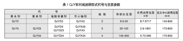
QJY series reducer is a hard-tooth surface (carburized, quenched tooth surface) crane reducer developed in response to market demand, including three types and 12 basic types
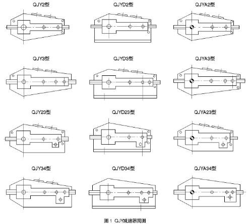
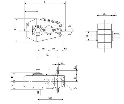
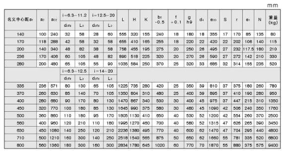
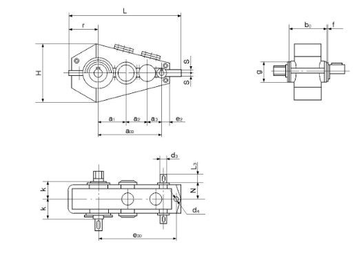
Its structure is shown in Figure 1, and its type code and main parameters are shown in Table 1.
2. Performance characteristics:
(1) The gears are made of high-quality low-carbon alloy steel, carburized, quenched, and gear accuracy is level 6.
(2) High precision, high efficiency, smooth transmission, low noise, smaller size, lighter weight, and high carrying capacity than quenched and tempered gear reducers (QJ series).
(3) Welded box structure.Installation type: three-point installation and foot installation.
(4) Output shaft type: flat key, involute spline, gear shaft end, hollow shaft.
(5)-Using oil tank lubrication, natural cooling, vertical reducer adopts circulating oil lubrication.
(6) Rolling bearings are used.
Application range:
1 The input speed is generally n1≤1500r/min.
2Working environment temperature -40-+50℃.
3 Positive and negative rotation.
It is suitable for the selection of various types of crane reducers.
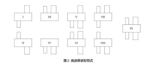
3. Assembly type (see Figure 2):
4. Installation type:
Type ajYD2, OJYD3, QJYD23, and OJYD34 adopt foot mounting.
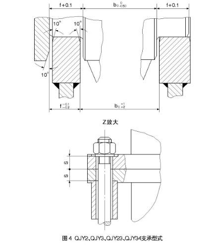
CJJY2、QJY3、QJY23、QJY34型采用三支点支承安装(安装方式见图4)
Two ways of horizontal W or vertical L are allowed (see Figure 3).
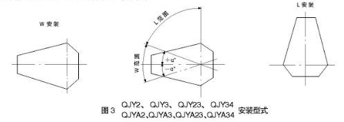
Note: a.The degree of the angle is related to the transmission ratio. When the reducer is inclined at angle a, ensure that the intermediate large gear is immersed in oil with a depth of 1-2 teeth height (the specific data of αo is determined by the user).
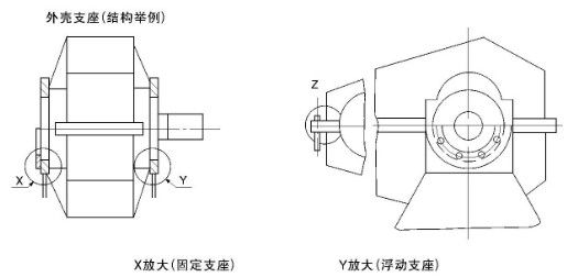
QJY2、QJY3、OJY23、QJY34型减速器支承型式见图4
Shell support (structure example)
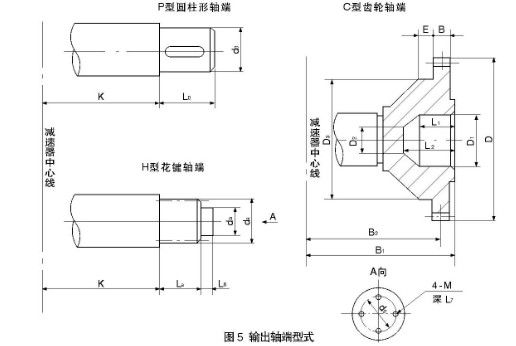
5. Shaft end type
The high-speed shaft end is connected with a cylindrical shaft extension and flat key.
Output shaft end P-cylindrical shaft extension flat key, single key connection;
H-cylindrical shaft extension involute spline connection:
c- Gear shaft end (only used for reducers with a center distance of 236-560mm.)
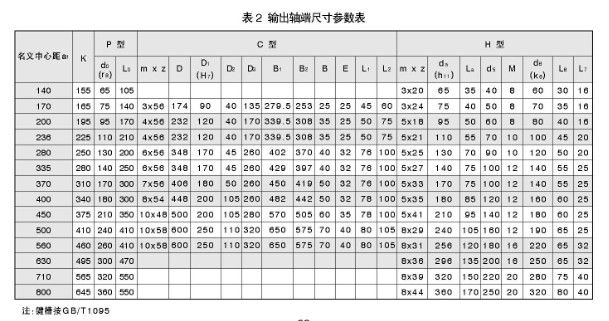
Shaft end structure type and size parameters are shown in Figure 5 and Table 2
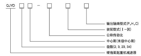
6. Code example:
Three fulcrum supporting crane reducer
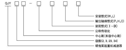
Markup example:
Crane reducer three-stage transmission, nominal center distance ai=560mm, nominal transmission ratio 50, assembly type 111, output shaft end is gear shaft end, horizontal installation is marked as: QJY3560-50IIICW
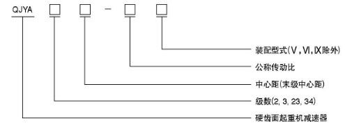
Crane reducer with base
Markup example
Crane reducer two-stage transmission, nominal center distance a, =560mm, nominal transmission ratio i=20, the fourth assembly type, the shaft end type is P type marked as: QJYD2560-20IVP.
Crane reducer with hollow shaft
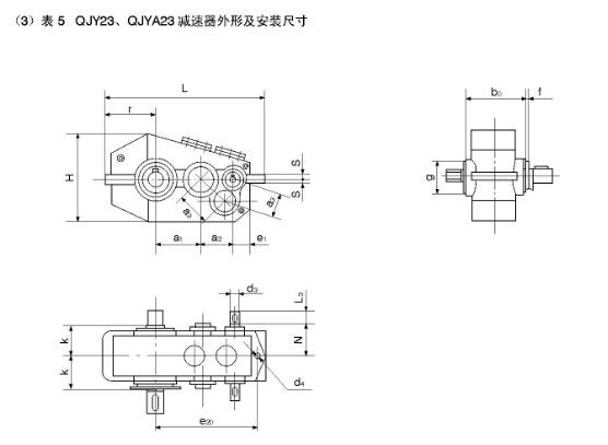
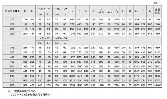
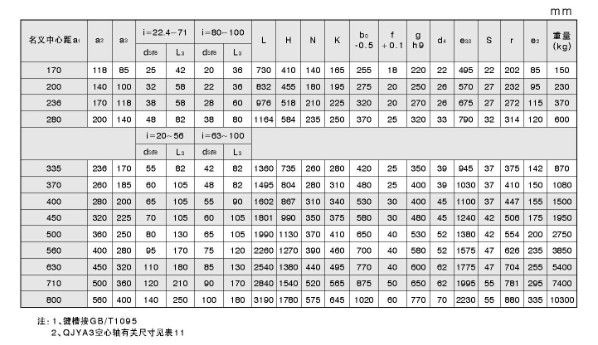
7. Shape and installation dimensions
(1) Table 3 QJY2, QJYA2 reducer outline and installation dimensions
(2) Table 4 QJY3, QJYA3 reducer outline and installation dimensions
(3) Table 5 QJY23, QJYA23 reducer outline and installation dimensions