
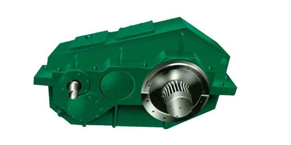
<一>QJ-LJ lifting vertical reducer
QJ-L type reducer is derived on the basis of QJ type reducer, which is mainly used for crane trolley operation mechanism and some gantry cranes, loading and unloading bridges and other large vehicles
In the running mechanism, it can also be used in the transmission of other equipment that requires vertical installation to replace the zsc type reducer.
1 Features
1) QThe JL type reducer adopts a cast iron box, and the base type side-mounted vertical reducer;
2) Three-stage transmission with a speed ratio of 16-100:
3) This series has 7 specifications, the nominal center distance is 140-400mm :
4) The small size reducer is lubricated by oil bath, and the reducer above 280 adopts centralized oil injection lubrication. Other features are the same as the QJ type reducer.
2 type
1) The structure type Qj-L type reducer is a three-stage vertical reducer with a base.
2) Assembly type Qj-L type reducer has six assembly types, as shown in Figure 11.
3. Model
3: Assembly type
2: Nominal transmission ratio
1: Nominal center distance
-L: Vertical with base
QJ: Crane reducer
Markup example
Crane vertical reducer, the nominal center distance is200 mm, The nominal transmission ratio is 40, the assembly type is the third type,
Marked as: reducer QJ-L200-40...
4 main technical parameters
1) Center distance The center distance of Qj-L type reducer is shown in Table 17.
2) Transmission ratio The transmission ratio of the QJ-L type reducer is shown in Table 18. The limit deviation between the nominal transmission ratio and the actual transmission ratio is ±5%.
5 Overall and installation dimensions
The appearance and installation dimensions of the QJ-L type reducer are shown in Figure 12 and Table 19.
6 bearing capacity
The output torque and the allowable power of the high-speed shaft of the QJ-L reducer when the working level is M5 are shown in Table 20.
The output torque of the QJ-L type reducer and the allowable power of the high-speed shaft during continuous operation are shown in Table 21.
The instantaneous allowable torque at the output shaft end of the reducer is 27 times the rated torque.
<XNUMX> QJ-T type crane packaged reducer
QJ-T type reducer is in aj-LIt is derived from the type reducer, which is mainly used in the operating mechanism of the crane, and can also be used in the transmission of other machinery that requires a vertical set, to replace the ZSC(A) type reducer.
1 Features
1) The output end of the QJ-T type reducer is a conical sleeve, and the reducer is sleeved on the passive shaft of the host, and its end is fixed, and the weight of the reducer is also supported on the shaft.A mounting hole is provided on the upper part of the box body, which is fixed on the bracket by a pin shaft.
2) The box body is divided into three parts, forming an "upper" shape for use as a vertical reducer. The lubricating oil in the lower box is not easy to leak, and the size from the center line of the output shaft to the lower limit position is relatively small.Other features are the same as Qj-L type reducer.
2 type
1) Assembly type QJ-T type reducer has four assembly types, as shown in Figure 13.
2) Shaft end type High-speed shaft adopts cylindrical shaft extension, flat key connection, low-speed shaft adopts hollow shaft sleeve, tapered shaft hole, flat key connection.
3 model
Markup example
Crane suit reducer, nominal center distance ai=200.Nominal transmission ratio i=40, assembly type III
Marked as reducer QJ-T200-40...
4 main technical parameters
The center distance and transmission ratio of QJ-T type reducer are the same as QJ-L type reducer.
3: Assembly type
2: Nominal transmission ratio
1: Nominal center distance
-T: suit type
QJ: Crane reducer
5 Appearance and installation dimensions
The appearance and installation dimensions of QJ-T type reducer are shown in Figure 14 and Table 22.
6 bearing capacity
The output torque of the QJ-T type reducer and the allowable power of the high-speed shaft are the same as those of the CJ-L type reducer, see Table 20 and Table 21.
<Three>.Selection method
1.Selection principle
1) When selecting a reducer, the working conditions must be met first.Namely, high-speed shaft speed, maximum gear peripheral speed, ambient temperature and steering, etc.
2) Meet the requirements of mechanical strength, such as the power of the input shaft (or the rotation of the shaft, the maximum radial force and the instantaneous maximum torque of the shaft extension, etc.). The thermal power must also be met for the continuously used reducer.
3) To meet the speed requirements, choose the closest transmission ratio according to the speed of the prime mover and the required speed of the working mechanism (preferably the actual transmission ratio of the reducer, if the actual transmission ratio is not given, use the nominal transmission ratio instead), generally two The limit deviation is ±2% for level 4 and ±3% for level 5.If you have special requirements, please contact the factory for special preparation.
4) Determine the structure, installation, and assembly types of the reducer according to the requirements of the main engine for the installation position, limit size, connection location, and transmission performance of the reducer.
5) According to the connection mode of input and output, select the type of shaft end.
6) Considering the convenience of use and maintenance, choose the position of the oil injection port, the oil discharge port, the lubrication method, and the heat dissipation.
2.Select calculation
1) QJ type (including QJ-D, QJ-L and QJ-T type), when used in various crane mechanisms, according to the provisions of GB3811 "Crane Design Specification" (hereinafter referred to as "Specification"), the working level of crane mechanism is divided into There are eight types of M1-M8, and the carrying capacity listed in this manual is M5 working level.When it is used in other working levels, it should be converted according to the formula.
pM5=pM1X112~kW
The allowable power value of the high-speed shaft (kW) in the formula pM5- reducer carrying capacity table:
pM,-Power value relative to Mi working level (kW):
i-Number of job levels 1-8:
2) The basic load Mmax of the fatigue calculation of each mechanism of the crane
a) Lifting and unbalanced luffing mechanism
Mmax=φ6MnNmφ6=1/2(1+φ2)
Where φ6 is a dynamic load factor:
Mn- rated torque of the motor (Nm);
φ2-lifting load factor, φ2=1-2, when the hoisting speed is high, the system rigidity is large, and the operation is violent, the value of φ2 is larger.
See Appendix B of the Specification.
b) Running and slewing mechanism
Mrnax_qffs.0BMn
In the formula, φ5-elastic vibration increase coefficient: φ5=1.5-1.7;
φ8-rigid dynamic load factor: φ8=1.2-2.0:
φ8 is related to the drive characteristics of the motor and the ratio of the moment of inertia on both sides of the calculated part.See Appendix P of the Specification.
c) Balanced luffing mechanism
c) Balanced luffing mechanism
The basic load of the fatigue calculation is taken as the equivalent variable amplitude static resistance moment of the part, and other parts are taken as the rated torque of the motor and transferred to the calculated part torque 1.3
-1.4 times.When the instantaneous maximum torque is lower than 27 times the rated torque, the static strength check may not be performed. When it exceeds 27 times, the static strength of the parts shall be checked.
Or choose a reducer with a larger frame size.
3) According to the fatigue calculation of the basic load and speed, the power value PM of the working level can be calculated
PM=Mmax.n/9550(kW)
In the formula, n-speed reducer input shaft speed (r/min)
If the working level is not M5, it can be converted to the M5 working level power PM5 according to the formula, and then select the reducer according to Pms, input shaft speed n and nominal transmission ratio i.