
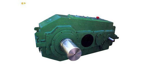
<XNUMX>Overview
The hard tooth surface reducer for QY series cranes is developed on the basis of the <medium hard tooth surface> reducer for QJ series cranes.The steel plate is welded, the box body is annealed to relieve stress, the gear is made of high-quality low-carbon alloy steel, the tooth surface is carburized and quenched, and is processed by the group grinding in the constant temperature workshop, and the product quality is stable and reliable.
<XNUMX> Applicable conditions
1 Gear circumferential speed is not more than 20m/m;
2 The speed of high-speed shaft is not too high at 1500r/min:
3 The working environment temperature is -40℃-+45'C;
4 It can run in both directions.
<XNUMX> Model and speed ratio
<four> mark
1.
1 Installation type
2 Low-speed shaft end type
3 assembly type
4 Nominal transmission ratio
5 Nominal center distance (low-speed center distance)
S: Three pivot support type
6 structure type
QY: Hard tooth surface reducer for crane
Mark down:
Nominal center distance a1=315, nominal transmission ratio i=56, assembly type 111th, low-speed shaft is gear shaft end vertical installation three-stage drive crane with hard tooth surface reducer, marked as reducer QY3S315-56IIICL
2.
Markup example:
Nominal center distance a,=315, nominal transmission ratio i=56, assembly type 111th, the low-speed shaft is the gear shaft end of the three-stage transmission crane with hard tooth surface reducer, QY3D315-56UⅢC.
<XNUMX> Assembly type, installation type, shaft end type
1 There are nine types of assembly types, as shown in Figure 1:
2QY3S、QY4S、QY34S型安装型式:卧式W或立式L(V)。在偏转角+a0范围内,为卧式安装;L范围内为立式安装。见图2
Note: The degree of angle a is related to the transmission ratio. When the reducer is inclined at angle a, it should be ensured that the intermediate gear is soaked in oil by 1-2
3QY3S、QY4S、QY34S型为三支点支承型式,见图3。
4.Shaft end type: the high-speed shaft end is connected with a cylindrical shaft extension and flat key, and there are three types of output shaft ends (see Figure 4 and Tables 2, 3)
a. Type P: cylindrical shaft extension, flat key, single key connection;
Type bH: Spline shaft extension, involute spline connection;
cC type: gear shaft extension (only the reducer with a nominal center distance of 180mm-560mm has this type of shaft end)
<XNUMX> Selection method of reducer
1 Determine the nominal transmission ratio of the reducer i.
Calculate the transmission ratio
is=n1/n2
Where: is the required transmission ratio;
n1, an input shaft speed, r/min:
n2, output shaft speed, r/min:
According to the required transmission ratio i. , Select the nominal transmission ratio i of the reducer. .
2.Determine the nominal input power PN of the reducer
PN>P2Xfixf2
Where: P. The rated power of the working machine kW;
f1 Working machine factor, selected from Table A according to the load status and utilization level of the working mechanism (refer to GB/T38T3811 Appendix N)
f2 a prime mover coefficient, electric motor and hydraulic motor fo=l.
}Check the maximum torque of the reducer
pN≥MnXnlXf3/9550
Where: Mn motor rated torque Nm:
f.The peak torque coefficient is selected from Table A according to the utilization level of the load condition of the working mechanism.
4.According to i.And PN select the specification model of the reducer from the power meter (table 10 or 11).
Example: A grabbing bridge crane for continuous loading and unloading with a lifting capacity of 32t and a span of 22.5m. The main lifting mechanism requires a static power of 50kW, a lifting speed of 8m/min, a speed of 18.5rmin, and the working level of the mechanism. M7: The rated power of the hoisting motor is 60kW, and the speed is 750r/min.Try to select the reducer (the third type of assembly, gear shaft end).
1) Calculate the transmission ratio:
is=n1/n2=750/18.5=40.5
Choose in=40, three-stage transmission
2) Determine the rated input power of the reducer:
PN≥P2XfiXf2
According to GB/T3811 Appendix N, the continuous loading and unloading grab bridge crane with working class M7, the main hoisting mechanism class is T6, the load condition is L3, look up table A, get f, =1.2
PN=50x1.2x1=60(klN)
When n=750r/min, iN=40, look-up table 10, ai355mm, allowable power of reducer high-speed shaft PN=74.9kW, which meets the requirements
3) Check the maximum torque of the reducer:
M、=9550XP1/n1=9550X60/750=764(Nm)
由L3-T6-M7查表A,起升机构f3=10