
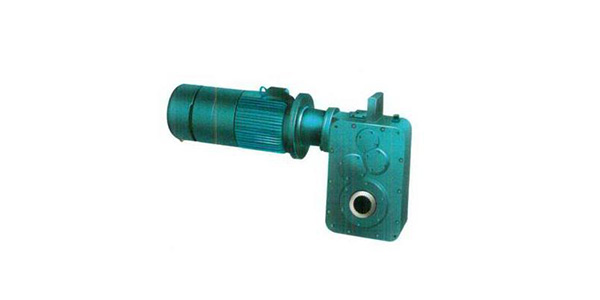
<XNUMX>Overview
The QS series reducer is a parallel shaft type reduction transmission device, which is designed by drawing on the advanced manufacturing experience at home and abroad.Mainly used for the operating mechanism of bridge cranes and large vehicles. The QSC series reducer is a vertically mounted reducer, which is mainly used for the operating mechanism of a gantry crane.The two series of products can also be used in the transmission mechanism of various mechanical equipment such as transportation, metallurgy, mining, petroleum, chemical industry, construction, railway, port, national defense engineering, light textile industry and so on.
1. Features
a. The supporting power range is large, and the deceleration range is wide.
b. Fast and simple assembly and adjustment.
c. The output shaft can be assembled on both sides for single drive or centralized drive.
d. Compact structure, beautiful appearance, small size and light weight.
e. Smooth operation and low noise
2. Applicable conditions
a. Gear circumferential speed≤20m/s
b. High-speed shaft speed ≤1500r/min
c. Working environment temperature: -40℃-45℃
d. It can run in both directions.
3. Model description
4: Output shaft type
3: Motor power and number of poles
2: Nominal transmission ratio
1: Machine seat number
(c): Vertical
QS: reducer code
Note: There are two types of output shaft: P-hollow flat key H-spline
<二>The appearance and installation dimensions of QS series reducer
1. Installation type
2. Shape and connection size
3. Allowable input shaft power and output torque
The input shaft speed is 1400r/min, the working level is M6 (920r/min can be equipped)
Note: Matching motor power: Nn<allowable power÷2-2.5
4. The input shaft speed is 1400r/min, continuous working type
Note: Matching motor power: Nn<allowable power÷2-2.5
<XNUMX> appearance and installation dimensions of qsc series reducer
1. Installation type
2. Shape and connection size
<XNUMX> Output shaft coupling size
1. Spline shaft (H)
2. Hollow balance shaft (P)
<XNUMX> Selection instructions for QS and osc series reducers:
According to the "Crane Design Specification" (GB3811-83), each crane mechanism has different working levels: 1 types from M8 to MB.The power meter listed in this series with the rate of M6l as the level of power meter, if other levels are used, should be converted according to the following formula
NMi=Nm6x1.12'6'(kW)
Where: i-work level
NMi-power value relative to M working level
Nm6-the allowable power value in the power meter
For the operating mechanism due to the large inertial load, the basic load for fatigue calculation is taken as the sum of the moment of inertia and the static moment of the calculated parts when the mechanism is started.
For the mechanism with small inertia load and fewer starting and braking times, the calculation result can be directly selected according to the power less than the table listed.However, in general operating mechanisms, the inertia load is relatively large, and frequent braking should be calculated based on the maximum vibration moment that the mechanism bears during braking. At this time, the meter power should be divided by the coefficient ψ5.
ψ5 Elastic vibration torque increase coefficient.
Considering that the working conditions of the heavy or extra-heavy crane operating mechanism are relatively harsh. (Organization is always in start-up, system working condition) It is appropriate to take ψ5=2_2.5
That is: NMl=ψ5Nn=(2_2.5)Nn
Where Nn- rated power of motor
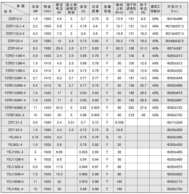
<XNUMX> Main technical parameters of matching motors for QS and QSC series reducers
Note: 1. The rated voltage is 380 volts and the frequency is 50 Hz.
2. Frequency-sensitive varistor can be selected when the winding motor is used for starting.
3. The rotor circuit of the wound motor can be used after the user has designed and configured the resistance, and it is not allowed to be used in a short circuit.
4. ZDY and YEJ motors are squirrel cage motors, and ZDR and YZRE motors are winding motors.
5. According to user requirements, variable speed motors, disc motors and other special motors can also be configured.