
<XNUMX> Overview:
This product is based on the People’s Republic of China Metallurgical Industry Standard YB/T050-93 "YNK Gear Reducer for Metallurgical Equipment". The four-stage vertical shaft hard gear is optimized and designed by the company’s reducer technology center with decades of superb technology. Face cone, cylindrical gear reducer.
<XNUMX>, the scope of application
1 The input speed is not too high at 1500 rpm.
2 The peripheral speed of the gear drive is not more than 20 meters per second.
3工作环境为-40-45℃。如果低于0℃,启动前应预热至0℃以上。
4Widely used in metallurgy, mining, chemicals, building materials, lifting, transportation, textile, paper, food, plastics, rubber, engineering machinery, energy and other industrial sectors.
<Three>, performance characteristics
1 The speed ratio range of the reducer is large: 90-500.
2 High mechanical transmission efficiency: greater than 91%.
3 gears are made of high-quality alloy steel by carburizing, quenching and finishing.
4Small size, light weight, high precision, large carrying capacity, high efficiency, long life, stable transmission and low noise.
5- Generally use oil pool lubrication and natural cooling. When the thermal power cannot be satisfied, circulating oil lubrication and cooling coil cooling can be used.
6 Easy to disassemble and inspect, easy to install.
<XNUMX>, reducer specifications and their representation
1 Specification: 272,305,340,385.430,480,545,610.680,770.860.960.1080,1210,1360
2 Representation method:
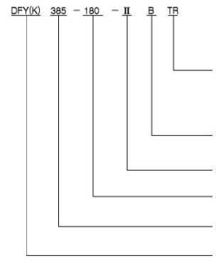
R: Rotation of the output shaft (viewed from the output shaft)
R-clockwise
L.Counterclockwise
T.Two-way rotation
TR-two-way rotation, the main rotation is clockwise
TL-two-way rotation, the main rotation is counterclockwise
D: Cooling method
Omitted-natural cooling
B- with cooling coil
D-Circulating oil cooling
I: Assembly type
315: Nominal transmission ratio
395: Specifications (total center distance of cylindrical gears on the midpoint surface)
DEY(k): Series code: K indicates that the output shaft is a hollow shaft
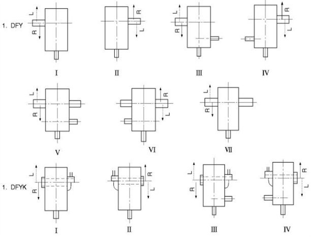
<XNUMX>, assembly type
According to the output shaft, DFY can be divided into seven assembly types I, II, III, IV, V, VI, VII, and DFYK can be divided into four assembly types I, II, III, and IV.Please specify when you need to equip the backstop (usually self-equipment).
<XNUMX> Classification of working machinery load:
The load of the driven working machine can be divided into: uniform load (u); medium shock load (M), strong shock load (H), and 24h continuous working conditions.See Table 8 for details (the load symbols listed in the table can be corrected after the details of the working conditions of the working machine are given).
<XNUMX> Selection methods and selection examples
The selection of the reducer refers to the selection method of ZFY and ZFYK.
Selection example
Example 1
Choose a conical cylindrical gear reducer for belt conveyor, known motor power P. =55kW, speed n, =1500r/min, nominal transmission ratio i=125, belt conveying bulk material, power has not been calculated in detail, slightly less than the motor power, working 8 hours a day, continuous operation, installation is greater than in the workshop, The heat dissipation conditions are good, the ambient temperature is 30°C, the assembly type is Type II, and the rotation direction of the output shaft is clockwise, which requires high reliability.
Choose reducer
a Determine the specifications of the reducer
From Table 8, the load of the block belt conveyor is M, check table 1, k=1.25, check table 2, Ks=112, check table 3, KR=1.6, and use the motor rate to replace the power of the working machine, P.= 55kW, therefore:
P.=P2.K,.Ks.KR_55xl.25xl12×1.6=123.2(kW)
Check table 14, choose DFY770, rated power 150kW, actual reliability coefficient KR. PN/(P2.KA.Ks)
=iso/(55xl.25xl.12)
= 1.948
b Check thermal power
Under given conditions, check Table 4, KT=1.15, check Yuan 5, Kw=00: From the power utilization coefficient Pg/P~xl55%=150/1000x35%=6%, check Table 1.3, KP=2, so 'P. , Blue P55-KTKWKP=15xl3xlxl.82.225=14(kW).Check table 70, the allowable power of the DFY/170 reducer installed in the large workshop is 70>P., after the above calculation, it is determined that the selected reducer code is DFY/125-XNUMX-IIR.
<XNUMX> Overall dimensions and carrying capacity of the reducer
The dimensions of 1DFY and DFYK reducers are shown in Figure 4 and Table 13;
2. The rated power and allowable thermal power of DFY and DFYK reducers are shown in Table 14;
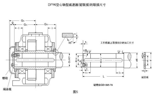
3. The connection dimensions of DFYK reducer hollow shaft with key coupling are shown in Figure 5 and Table 15;
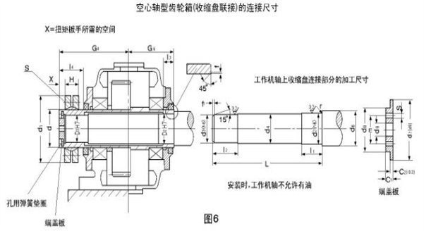
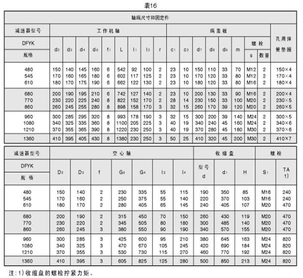
4. The connection dimensions of the hollow shaft of the DFYK reducer connected with the shrink disk are shown in Figure 6, Table 16.
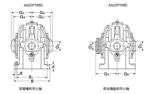
Note:
1 shaft extension end with key press GB1095-79
2D2、D3、G4、G5、G6及空心轴的连接尺寸见表15,表16。
3 When an output shaft with shaft extension at both ends is used, the shaft extension at the other end has dimensions G2, L2, and d2.
4 When the assembly method III-VI is adopted, please consult the factory for the dimension of the shaft extension of the intermediate shaft.
Nine, installation, use and maintenance
1 The axis of the input shaft and output shaft of the reducer, as well as the axis of the connecting part, should be coaxial, and the error should not be greater than the allowable value of the coupling used.
2 After installation, the required lubricating oil must be injected into the oil sump of the box body, and the oil level should be at the height between the upper and lower engraved lines specified by the oil dipstick.
3 The reducer must be turned by hand before it is officially used, and it must be flexible and free from jamming.Then carry out no-load operation for no less than 2 hours.The operation should be stable, and there should be no shock, vibration, noise, or oil leakage. If any fault is found, it should be eliminated in time.
4 When the new reducer is used for the first time, it must be replaced with new lubricating oil after 20 days of operation.In the future use, the oil level should be checked regularly.If it is lower than the specified height, make up in time.Under normal circumstances, the oil must be changed every three months for the reducer that works continuously for a long time, and the oil must be changed every six months for the reducer that works less than eight hours a day.
5 oil selection
环境温度:-10℃-0℃时用L-CKC68-L-CKC100(原N68-N100)润滑油
0℃-40℃时用L-CKC100-L-CKC320(原N100-N320)润滑油
6 When it is found that the oil temperature rises significantly during use, the temperature rise exceeds 60°C or the oil temperature exceeds 85°C, or abnormal noise occurs, stop using it and check the cause.If it is caused by tooth surface glueing, etc., it must be repaired, troubleshooting, and the lubricating oil replaced before use.
7 If severe oil leakage or oil leakage is found on the joint surface during use, open the machine cover and apply 601 sealant. If oil leakage is found, please replace it according to the crude oil seal model.