<一>The use, performance characteristics and model mark of the reducer
1.1 Purpose
The conical cylindrical gear reducer (hereinafter referred to as the reducer) is used for transmissions in which the input shaft and the output shaft are arranged in a vertical direction.Mainly used in belt conveyors and various transportation machinery, but also in coal metallurgy, mining, chemical building materials, light industry.In the transmission mechanism of various general machinery such as petroleum.
1'2 performance characteristics
High carrying capacity, low noise, small size, light weight, high efficiency and long service life.
1 Parameter range
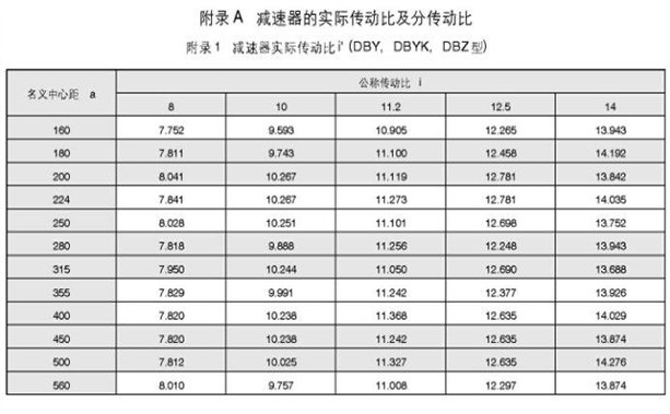
DBY, DBYK, DBZ type reducers each have 12 specifications, the nominal center distance is: 160, 180, 200, 224, 250, 280, 315, 355,400, XNUMX
450, 500,560 mm:Each specification has 5 transmission ratios (8, 10, 112, 125, 14), two kinds of rotation and four assembly types respectively constitute 240 kinds of reducers.
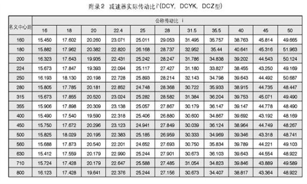
There are 15 specifications for DCY, DCYK, and DCZ reducers. The nominal center distances are: 160, 180, 200, 224, 250, 280, 315, 355,400, XNUMX.
450, 500,560,630,710 ,800 mm: Each specification has 11 transmission ratios (16, 18, 20, 22.4, 25, 28, 315, 35.5, 40,45, 660), two rotation directions, four assembly types, and XNUMX types of reducers are formed.
This series of reducers can meet all the power requirements of TD and DX belt conveyors and other transportation machinery and 0.8-6.5m/s Working range with speed.
1.4 Structure
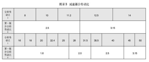
The first-stage transmission of the reducer is the second-stage spiral bevel gear made by Gleason, and the third-stage transmission is the involute cylindrical helical gear.
Lubrication of the reducer: In general, the gears and bearings of the reducer are naturally cooled by splash lubrication from an oil pool.Only when the working equilibrium temperature of the reducer exceeds the specified value or the carrying power exceeds the thermal power pG, the circulating lubrication or the oil pool lubrication with cooling pipe is used.
1.5 Model and marking
The model of the reducer is composed of the type code, the nominal center distance a (the center distance of the final stage), the nominal transmission ratio, the assembly type code, and the input shaft rotation direction code.
D-belt conveyor group code is B-two-stage transmission, c-three-stage transmission, Y-hardened gear, Z-medium hardened gear, K-output shaft is of hollow shaft type.
Nominal center distance, expressed in actual numbers in mm
The transmission ratio is expressed by the nominal transmission ratio.
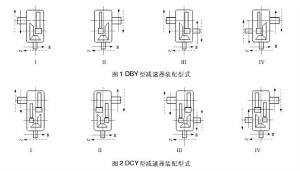
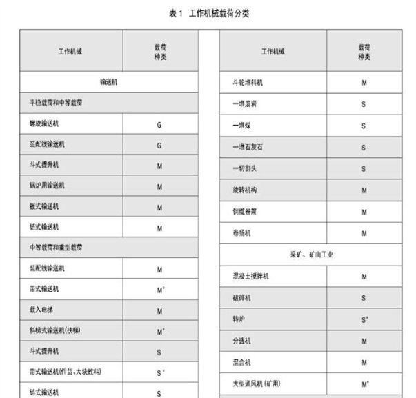
The assembly type is indicated by Roman numerals I, II, III, and IV.
The direction of rotation of the input shaft: when viewed from the direction of the input shaft, S is clockwise and N is counterclockwise
mark

Markup example:
The nominal center distance is280 mm, The nominal transmission ratio is 315, the assembly type is the first..., the input shaft is clockwise rotating three-stage transmission. The deceleration is marked as: reducer DCY280-31.5 a...SJB/T9002-1999
16 assembly type.
According to the output shaft, it can be divided into four assembly types: I, II, III, and IV. Type I|| is the type without backstop, and type Ⅲ and Ⅳ are the type with brake f backstop.The structure diagram is shown in Figure 1, Figure 2, Figure 3, Figure 4.

<XNUMX>Scope of application
21 The maximum speed of the input shaft is not more than 1500r/min;
22 Gear peripheral speed is up to20m/s;
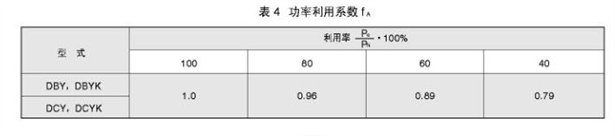
23 Working environment temperature is -40-+45 ℃; When the ambient temperature is lower than0 ℃The lubricating oil should be heated to +10 ℃.
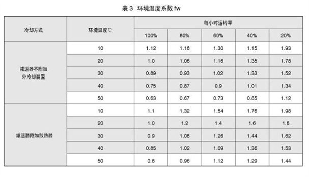
<XNUMX> Classification of Work Machinery Loads
The load of the driven machine can be divided.Smooth load (G), medium shock load (M), heavy shock load (S) and work that always works continuously for 24 hours a day
(0).See Table 1 for details.
<XNUMX> Overall dimensions and carrying capacity of the reducer
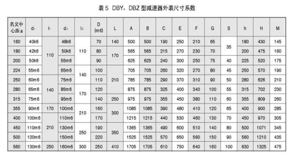
The dimensions of 51DBY and DBZ reducers are shown in Figure 5 and Table 5.
5.2 DBY, DBYK type reducer load capacity and thermal power, see Table 6 and Table 7.
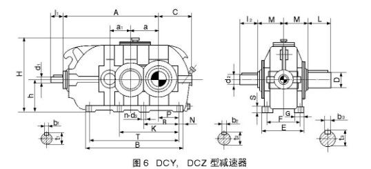
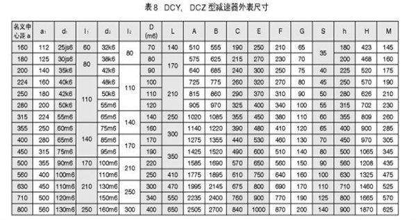
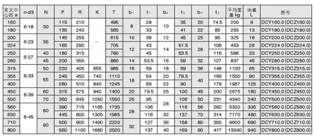
5.3 The external dimensions of DCY and DCZ reducers are shown in Figure 6, Table 8.
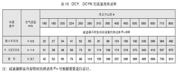
5.4 DCY, DCYK type reducer carrying capacity and thermal power, see Table 9 and Table 10.
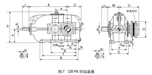
5.5 DBYK type reducer outline dimensions, see Figure 7, Table 11.
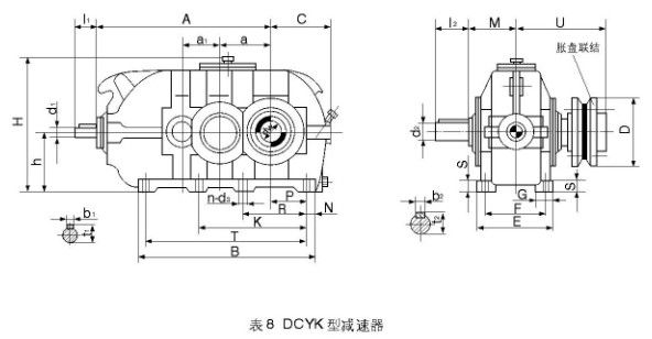
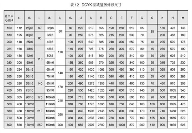
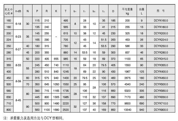
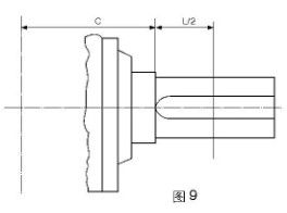
5.6 External dimensions of DCYK type reducer, see Figure 8, Table 12.
5.7 The bearing capacity of DBZ type reducer is shown in Table 13.
5.8DCZ type reducer load table 1


<XNUMX> Radial load of reducer shaft extension
6 1 The rated radial load h at the midpoint of the input shaft extension is according to formula 6
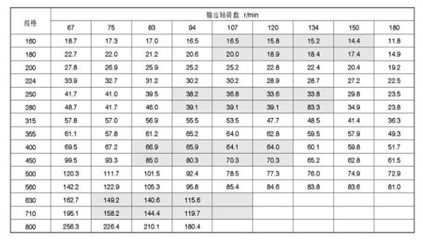
6 2 The rated radial load tz at the midpoint of the output shaft extension is selected according to Table 15.

Note:
1 This table is suitable for DBY, DCY type reducer
2 When the output shaft revolution is between the listed revolutions, the allowable radial load is calculated by interpolation;
3 When the number of output shaft revolutions is less than the minimum number of revolutions listed in the table, the allowable radial load is selected according to the maximum value of the specification.